
Installation of FRP Systems
Introduction
In an aggressive environment, concrete may be vulnerable to chemical attacks, such as carbonation and chloride contamination which break down the alkaline barrier in the cement matrix. Consequently, the steel reinforcement in concrete structures becomes susceptible to corrosion. Such phenomena lead to delamination of the concrete at the reinforcement level, cracking and spalling of the concrete due to the volume increase of the steel reinforcement. In the United States, nearly one-third of the nation’s 581000 bridges are considered structurally deficient or functionally obsolete. A large number of these deficient bridges are reinforced or prestressed concrete structures, and are in urgent need of repair and strengthening. In the United Kingdom, over 10,000 concrete bridges need structural attention. In Europe, the cost of the repair of reinforced concrete structures because of corrosion of reinforcing bars is estimated to be over $600 million annually. In Canada, it is estimated that the required repair costs for parking garages alone is in the range of $6 billion. A possible solution to combat reinforcement corrosion for new construction is the use of non-corrosive materials to replace conventional steel bars. High tensile strength, lightweight and corrosion-resistant characteristics make FRP ideal for such applications. FRP also provides a practical technique for the repair and strengthening of concrete structures and bridges by using externally bonded sheets or prefabricated laminates. FRP tendons can also be used to strengthen old prestressed concrete girders.
Design philosophy
The use of FRP materials as reinforcement for concrete structures requires the development of design procedures that ensure adequate safety from catastrophic failure. Design recommendations for concrete members reinforced or strengthened with FRP are based on limit states design principles. Design of concrete members reinforced with FRP is based primarily on the required strength and then checked for serviceability criteria, fatigue endurance, and creep rupture endurance. In many instances, serviceability criteria, fatigue and creep rupture endurance limits may control the design. With steel reinforcement, a confident level of safety is always provided by yielding of the steel reinforcement of section/subjected to flexural loads. Owing to the linear elastic behavior of FRP materials, flexural, shear and bond failures are unavoidably sudden and brittle. Current building codes and design specifications for FRP recognize the advantages and disadvantages of these materials and define analytical procedures which engineers can use for design[I6). The current design guidelines of ACI[2o,2tJ are introduced with conservative strength reduction factors to be compatible with the specific performance limitations of FRP materials. The ultimate strength limit states for FRP (flexure, shear rupture, or debonding) are described below.
FLEXURAL FAILURES
Flexural design of reinforced/strengthened concrete members with FRP materials proceeds from basic equilibrium on the cross-section and constitutive behavior of the concrete and the FRP. The stress in the FRP reinforcement continues to increase with increasing strain until the FRP reinforcement ruptures.
Flexural failure modes in concrete structures reinforced with FRP
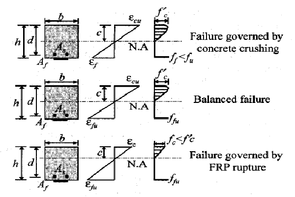
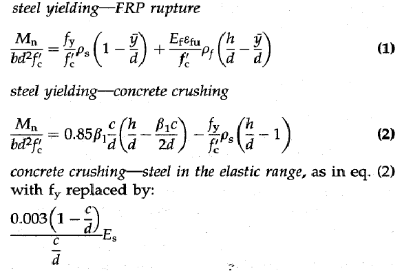
Research studies have shown that properly designed reinforced concrete members with FRP or strengthened steel reinforced members may fail in bending according to one of the following failure mode sequences: steel yielding followed by FRP rupture, or steel yielding followed by concrete crushing. For cases where the total area of steel and FRP reinforcement were relatively high, a third failure mode was observed to occur, in which the concrete crushed in a catastrophic manner. Different flexural failure modes are shown in Fig. 3. The nominal moment capacity Mn corresponding to these failures can be expressed by:
Flexural Design equations
where c is the depth of the neutral axis from the extreme compression fiber; b is the width of the crosssection; d is the depth from the extreme compression fiber to the centroid of the steel reinforcement; h is the depth from the extreme compression fiber to the externally bonded FRP reinforcement; 9 is the . distance from the centroid of the concrete stress block to the FRP; PI is an empirical constant which depends on the concrete compressive strength; Ps and Pf are the reinforcement ratios of steel and FRP reinforcement, respectively, defined as As-steer/bd and AFRP Ibh; Es and Ef are the elastic moduli of the steel and FRP reinforcement, respectively; Gfu is the tensile failure strain of the FRP; fy is the yield strength of the steel reinforcement and f~ is the nominal compressive strength of the concrete at 28 days. Research studies on concrete members reinforced or strengthened with FRP materials indicated a sudden and brittle failure mode when the FRP reinforcement ruptured in tension. A more progressive and less catastrophic failure with a higher deformability factor was observed when the failure was governed by crushing of the concrete after yielding of the internal steel reinforcement. The use of high-strength concrete allows for better use of the high-strength properties of the FRP materials and increases the stiffness of the cracked section, but the brittleness of high-strength concrete compared with normal-strength concrete can reduce the overall deformability of the flexural member. Conservative strength reduction factors should be adopted to provide a higher reserve strength in concrete members reinforced or strengthened with FRP. The Japanese recommendations for design of flexural members using FRP suggest a strength reduction factor for FRP materials equal to 1/1.3. Other researchers in Canada suggest a value of 0.75, determined on the basis of probabilistic concepts. The American Concrete Institute suggests a strength reduction factor of 0.5 for rupture controlled failures and a value of 0.7 for concrete crushing failures. It should be mentioned that direct comparisons of these numbers should not be made because these strength reduction factors correspond to different load factors in the respective countries.
SHEAR FAILURES
Shear failures are typically brittle and should be avoided as a failure mode for concrete members reinforced or strengthened with FRP. Shear failure modes of members with FRP as shear reinforcement can be classified into two types: shear-tension failure mode (controlled by the rupture of FRP shear reinforcement) and shear-compression failure mode (controlled by the crushing of the concrete web). The first mode of failure is more brittle, and the latter results in larger deflections.

Various shear strengthening configurations with FRP
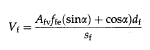
Experimental results have shown that the modes of failure depend on the shear reinforcement index Pfv Ef, where Pfv is the ratio of FRP shear reinforcement to the effective cross-sectional area and Ef is the modulus of elasticity of the FRP stirrups. As the value of pfvEf increases, the shear capacity in shear-tension increases and the mode of failure changes from shear-tension to shear-compression. The current design assumption that concrete and reinforcement capacities can be added to estimate the shear capacity of the member is accurate when shear cracks are adequately controlled. Therefore, the tensile strain in the FRP shear reinforcement should be limited to ensure that the design approach is applicable. The Canadian Highway Bridge Design Code limits the tensile strain in FRP shear reinforcement to 0.2%. A pan-European collaborative research programmer EUROCRETE conducted a series of research and demonstration projects, which limit the value of the shear strain in FRP reinforcement to 0.25%. Members with FRP longitudinal reinforcement and steel stirrups did not experience unusual shear behaviour. Special attention should be devoted to the reduced dowel contribution of the FRP reinforcement out of plane in the presence of shear cracks. External shear reinforcement in the form of bonded FRP overwrap has been applied to beams with insufficient shear strength. This procedure can provide sufficient shear resistance, depending on the amount and the configuration of the externally bonded FRP reinforcement, and allow full development of the flexural capacity of the beam. For concrete members strengthened in shear using externally bonded FRP sheets, loss of aggregate interlock of the concrete has been observed to occur at fiber strains less than the ultimate fiber strain. To preclude this mode of failure, the maximum strain recommended for design by ACI Committee 440 is limited to 0.2%. The same approach was applied in the Canadian and the European Standards. Recently, many shear-strengthening configurations have been proposed to increase the shear capacity of reinforced concrete beams through FRP retrofit. Multiple options exist for shear strengthening, as shown in Fig. 4, including laminate bonding to the sides of the beam, V-jacketing around the bottom, and total wrapping of the beam. The shear-resisting system can be in the form of continuous sheet or laminates with spacing. Fibres can be oriented either perpendicular to the axis of the beam or perpendicular to the potential shear cracks, or a combination of both orientations. The contribution of shear strength provided to a member by the FRP system is based on the fibre orientation and an assumed crack pattern and can be expressed as:
Shear designing of FRP systems
where Afv is the area of the FRP shear reinforcement; ffe is the effective stress in the FRP, taken as the smaller of the design tensile strength ffu or the stress corresponding to 0.002 Ef; Ef is the modulus of elasticity of FRP; df is the depth of the FRP shear reinforcement; Sf is the spacing of the FRP shear reinforcement and tX is the angle of inclination of the FRP shear reinforcement. The nominal shear capacity of concrete members reinforced or strengthened with FRP in shear can be determined by adding the full contribution of the FRP reinforcement to the contributions from the reinforcing steel and the concrete.
DEBONDING FAILURES
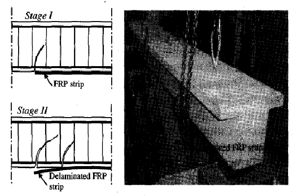
Debonding failures are very common in concrete members retrofitted with externally bonded FRP systems. These types of failures are often brittle, occur with little or no visible warning, and take place at load levels significantly lower than the flexural or shear strength of the retrofitted system. For FRP sheets/strips in bending, this mode of failure initiates with a horizontal crack atone of the edges of the bonded FRP sheets/strips below the internal steel reinforcement level and/propagates toward mid-span, leading eventually to a complete separation of the FRP with the adjacent concrete cover layer.
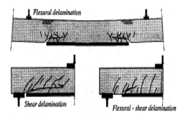
Delamination from existing shear cracks is characterized by differential vertical displacements at crack tips in retrofitted concrete beams. Such a phenomenon causes a stress intensity in the bond region, which initiates fracture and results in delamination propagation under increased loading. Debonding failures are characterized by propagation of the failure process parallel to the plane of the laminate, while other failures such as flexural or shear failures propagate perpendicular to this plane. Debonding includes failure of the concrete layer between the FRP and the flexural steel followed by delamination or peeling of the FRP from the concrete. Three identified debonding failure mechanisms categorized by many researchers are illustrated in the figure below.
delamination failure modes
Theoretical work on the bond strength and delamination models can be simplified into three main categories:
empirical models, based directly on regression of test data[31,321. Various relationships were proposed relating the bond length of the FRP sheets/strips to the average bond strength. These models underestimated the bond strength and led to large scatter;
Mechanics of materials approach in which the elastic stress field at the termination point of the FRP materials was analysed. The interfacial shear stresses between the FRP sheets/strips and the adhesive were calculated by considering the equilibrium of an infinitesimal portion of the FRP. These types of solution assume linear elastic behaviour of both concrete and adhesive. Consequently, such type of analysis is limited to regions of low damage, such as inflection points where the normal stresses are generally low;
Fracture mechanics approach. Quantitative studies of FRP delamination through fracture mechanics concepts offer great potential in understanding the role of relative materials and design properties on the overall failure process through delamination. Interfacial fracture mechanics can be used to characterize crack tip stresses, crack propagation, and crack path evaluation. However, the use of interfacial fracture mechanics with laminated concrete structures has been limited. Many experimental programs, reporting debonding failures in the literature do not have provisions for detecting the exact origin, propagation, and secondary mechanisms involved with the debonding process. Thus, an improved experimental technique for monitoring debonding failure is needed. ACI Committee 440 design guidelines recommend a maximum elongation limit for the design of FRP sheets/strips to avoid peeling of the FRP reinforcement based on experimental results conducted by other researchers. The document also includes some detailed provisions dealing with delamination failures.
FRP strengthening techniques
EXTERNALLY BONDED FRP SYSTEMS
The most imperative characteristic of externally bonded FRP systems in repair/strengthening applications is the speed and ease of installation. FRP may be bonded to the tension side of concrete beams, girders and slabs to provide additional flexural strength, and/ or on the sides of beams and girders to provide additional shear strength. For seismic zones, FRP may also be used to wrap columns to enhance the ductility due to the induced confinement of the concrete. FRP material selection should be based on strength, stiffness and durability required for a specific application. Resins are selected on the basis of the environment to which the FRP will be exposed, as well as the method by which the FRP is manufactured. FRP plate bonding technology was first investigated at the Swiss Federal Laboratory for Materials Testing and Research (EMPA). FRP composites have been used in other areas such as the aerospace industry for many years and their superior properties compared with other conventional structural materials are well known. Externally bonded FRP systems come in a variety of forms, including wet lay-up systems and procured systems. Wet lay-up FRP systems consist of dry unidirectional or multidirectional fibre sheets or fabrics impregnated with a saturating resin on-site. Precured FRP systems consist of a wide variety of composite shapes manufactured off-site. Typically, adhesive along with the primer and putty are normally used to bond the precured shapes to the concrete surface. The primer is used to penetrate the surface of the concrete, providing an improved adhesive bond for the saturating resin or adhesive. The putty is used to fill small surface voids in the substrate and to provide a smooth surface to which the FRP can bond. Precured FRP systems include unidirectional laminates, multi-directional grid and precured shells.
Delamination of externally bonded FRP reinforcement
Since 1982, externally bonded FRP sheets/strips have been successfully applied to reinforced concrete beams. Researchers worldwide suggest that FRP sheets / strips could replace externally bonded steel plates with overall cost savings emanating from the simplicity of the strengthening method. Externally bonded FRP sheets and strips are currently the most commonly used techniques for strengthening bridges and concrete structures. In spite of the significant research being reported on their structural mechanism and performance, there are still heightened concerns regarding possible premature failure due to debonding, especially in zones of combined high flexural and shear stresses.
Delamination failure of externally bonded FRP sheets is illustrated in Fig. 6. In addition, externally bonded FRP reinforcement is relatively unprotected against wear and impact loads. The structural performance of the externally bonded FRP could also be greatly affected by harsh environmental conditions.
NEAR-SURFACE-MOUNTED FRP SYSTEMS
Use of near-surface-mounted (NSM) FRP rods and strips can preclude delamination-type failures, frequently observed by using externally bonded reinforcement. FRP bars or strips can be inserted in specially constructed grooves within the concrete cover layer, and adhered to the concrete with epoxy adhesives as shown in Fig. 7. The NSM technique becomes particularly attractive for flexural strengthening in the negative moment regions of slabs and decks, where external reinforcement would be subjected to mechanical and environmental damage and would require protective cover, which could interfere with the presence of floor finishes. NSM steel bars have been used in Europe since 1947. Tests on concrete beams reinforced with steel bars and others reinforced with steel bars grouted into diamond-sawn grooves showed identical behaviour for both sets of specimens. Flexural or shear strengthening with NSM FRP strips showed a greater anchoring capacity compared with externally bonded FRP strips. The feasibility of NSM FRP bars and strips have been investigated experimentally by many researchers. Test results showed that the efficiency of NSM FRP strips, defined as the ratio of the percentage increase in capacity to construction cost, was three times that of the externally bonded strips. A general methodology to evaluate the development length of NSM FRP bars of different configurations was investigated by the authors. The model is based on equilibrium and displacement compatibility procedures using finite element analysis, and accounts for distinct characteristics of concrete, epoxy and FRP materials. Fig. 8 shows a schematic representation of the principal tensile stresses around a NSM FRP bar. The development length is highly dependent on the dimensions of the strips, concrete properties, adhesive properties, internal steel reinforcement ratio, reinforcement configuration, type of loading, and groove width.

Strengthening procedures with NSM FRP bars
Two different types of debonding failures can occur for NSM FRP bars. The first mode of failure is due to splitting of the epoxy cover as a result of high tensile stresses at the FRP-epoxy interface, and is termed ‘epoxy split failure’. Increasing the thickness of the epoxy cover reduces the induced tensile stresses significantly. Furthermore, using adhesives of high tensile strength delays epoxy split failure. Epoxy split failure usually forms with longitudinal cracking through the epoxy cover. The second mode of failure is due to cracking of the concrete surrounding the epoxy adhesive and is termed ‘concrete split failure’. This mode of failure takes place when the tensile stresses at the concrete-epoxy interface reach the tensile strength of the concrete. Widening the groove minimizes the induced tensile stresses at the concrete-epoxy interface and increases the debonding loads of NSM bars.
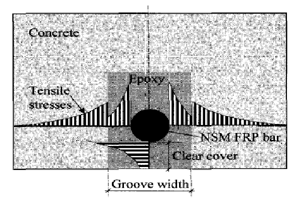
Typical tensile stress distribution around a NSM FRP bar
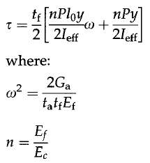
Analytical modelling for NSM FRP strips is based on the combined shear-bending model for externally bonded FRP plates. The model is modified to account for the doubly bonded area of NSM strips. The model accounts also for the continuous reduction in flexural stiffness due to cracking of the concrete. Debonding of NSM FRP strips occurs as a result of the high shear stress concentration at the cut-off point. For simply supported beams subjected to a concentrated load P, at mid-span, the shear stress at the strip cut-off point r can be expressed in terms of the effective moment of inertia, Jeff, and the thickness of the FRP strip, tf, as follows:
NSM equations
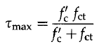
Ef is the elastic modulus of the FRP strip, Ec is elastic modulus of concrete, Ga is the shear modulus of the adhesive, fa is the thickness of the adhesive, 10 is the unbonded length of the strip and Y is the distance from the strip to the neutral axis of the transformed section. Premature debonding of NSM FRP strips is governed by the shear strength of the concrete. Other components of the system such as the epoxy adhesive and the FRP strips have superior strength and adhesion properties compared with concrete. Knowing the compressive and tensile strength of concrete, the Mohr-Coulomb line, which is tangential to both Mohr’s circles for pure tension and pure compression, can be represented, and the maximum critical shear stress for the pure shear circle can be expressed as:
NSM equations 2
where Ie is the compressive strength of concrete after 28 days and let is the tensile strength of concrete. Debonding loads for NSM FRP strips can be determined for simply supported beams loaded with a concentrated load at mid-span by equating the shear strength proposed in eq. (7) to the shear stress given in eq. (4), Other loading cases (e.g. simply supported beams subjected to a uniform load, simply supported beams subjected to two concentrated loads) are reported. In general, strengthening limits for concrete members retrofitted with FRP should be specified, such that a loss of FRP reinforcement should leave the concrete member with sufficient capacity to resist at least unfactored dead and live loads.