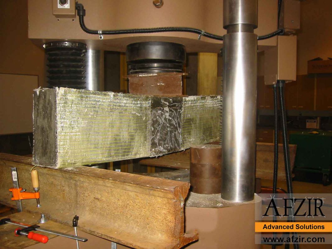
FRP TEST METHODS
The construction process is critical to obtaining the strength increases provided by the FRP. Quality control is critical because the weakest location controls the usable strength increase. Consequently, as FRP materials are manufactured, a quality-control program must be implemented to assess and monitor the properties of the material. There are many test methods available to determine the properties of composite materials. However they are not fully exploited and standardized yet as it is with metals. The differences in the properties of two testing media are presented in the Table below. Other reasons for variations in the test data are: the chosen test method, the specimens design, the composite fabrication method and the void content.
Differences in the properties of steel & FRP test
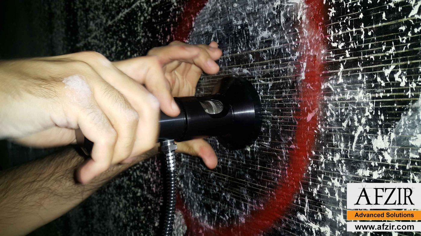
This test is a common test for FRPs that are already installed on concrete. The results of this test provide the construction team with valuable data about the coherence between FRP and the surface. It always evaluated the performance of the FRP resin.
This test could be conducted everywhere it was needed, with no inconvenience. it is also applicable for horizontal and vertical surfaces.
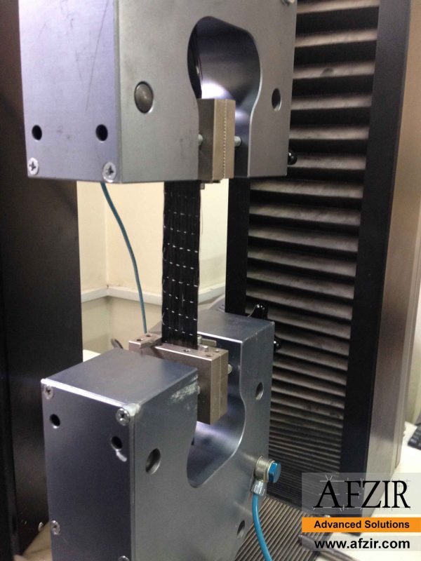
Standard test method for testing polymer matrix composites that allows in-plane tensile properties to be determined. Rectangular coupons are placed in the grips of the mechanical testing machine (for example Instron 4505) and monotonically loaded. The maximum force before specimens failure allows for an ultimate strength calculation. When using strain gauges, the stress-strain response can be recorded and this allows deriving the ultimate tensile strain, the tensile modulus of elasticity, Poisson ratio, and transition strain for specimens that show a bilinear response. Tensile unidirectional (carbon or glass)specimen geometry recommendations are 25 mm in length, 15 mm in width and 1.5 mm in thickness.
The standard method also emphasizes the use of tabs when testing unidirectional specimens to prevent gripping damage and premature failure (ASTM D3039, 2008). However, for detailed guidelines refer to the complete ASTM D3039 standard which goes step by step through sample preparation and testing. Standard method described by ASTM D3039 gives also guidance for analyzing tensile data for three strain gauges set up that is summarized in Section 4.5. It is important to mention that close attention has to be paid to factors affecting the tensile response and any deviations needed to be reported as they can have a significant impact on the final results. These include, but are not limited to:
- the material itself;
- the materials preparation and lay-up;
- the specimens curing;
- the environment of preparation of specimens and testing;
- the specimens alignment and gripping;
- the rate of testing;
- the void content (ASTM D3039, 2008).
It is important to recognize that one of the crucial factors in determining FRP parameters is its failure. Therefore, general overview of the FRP failure in terms of its structure is described below at different levels, with a discussion leading to failure modes issues associated with the Tensile Testing of FRP Composites according to ASTM D3039 standard. Having a detailed, background knowledge on failure modes at the microscopic and macroscopic levels with associated factors, it is necessary to introduce typical failure modes associated with tensile testing of FRP Coupons. ASTM distinguishes nine typical failure modes presented in below.

FAILURE MODES ACCORDING TO ASTM D3039
These modes are classified according to the failure type, the failure area and the failure location. When these three characteristics are determined, the sample is assigned a three letter code, where each letter corresponds to specific failure character (the following table).
Tensile Test Failure Codes (ASTM D3039, 2008)
American Society for Testing and Materials (ASTM) Standards
- Test standards for polymer matrix and metal matrix composites – ASTM Vol. 15.03 Space Simulation; Aerospace and Aircraft; Composite Materials
- Test standards for ceramic matrix composites – ASTM Vol. 15.01 – Refractories; Activated Carbon; Advanced Ceramics
Direct measurement of fiber longitudinal properties Ef1 and Sf1(+)
 Different ways of mounting fiber specimens on backing strip. (From ASTM
Standard C 1557-03R08)
Different ways of mounting fiber specimens on backing strip. (From ASTM
Standard C 1557-03R08)Different failure modes for resin-impregnated strand test specimens. (From ASTM
Standard D4018-99(2008))
Indirect measurement of fiber transverse modulus Ef2
Diametric compression of fiber for measurement of fiber transverse Young’s modulus. (From Kawabata, S. 1989. In Vinson, J.R. ed., Proceedings of the 4th Japan–U.S. Conference on Composite Materials, pp. 253–262. CRC Press, Boca Raton, FL. With permission.)
Tensile measurement of neat resin properties Em and Sm1(+)
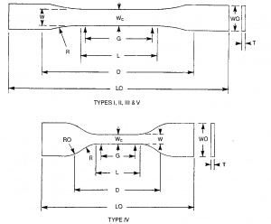
ASTM D638-10 Type I, II, III, IV and V neat resin tensile specimen geometries.
(From ASTM Standard D638-10).
Removal of resin matrix from composite sample by either chemical digestion with acids or other chemicals (carbon fiber composites), or resin burn-off in a furnace (glass fiber composites) according to ASTM Standard D3171-09
Computer-aided image analysis of digital photomicrographs to determine fiber area fractions of polished composite specimens.

Effect of end conditions on deformation of an off-axis tensile specimen
Exhibiting shear coupling. (From Pagano, N.J. and Halpin, J.C 1968.
Journal of Composite Materials, 2, 18–31. With permission.)
(From ASTM Standard D3410/D3410M-03 (Reapproved 2008). Copyright ASTM International. Reprinted with permission.)


